UART - Part 2
Consider our boilerplate:
#![no_std]
#![no_main]
use esp_hal::{main, Config};
use esp_backtrace as _;
use esp_println as _;
esp_bootloader_esp_idf::esp_app_desc!();

#[main]
fn main() -> ! {
  let peripherals = esp_hal::init(Config::default())
  loop {}
}
How do we get to use a UART peripheral from there? How do we configure the peripheral? Which configuration options do you expect? Try getting a sense of what to do first (maybe checking esp_hal docs.)
Warning
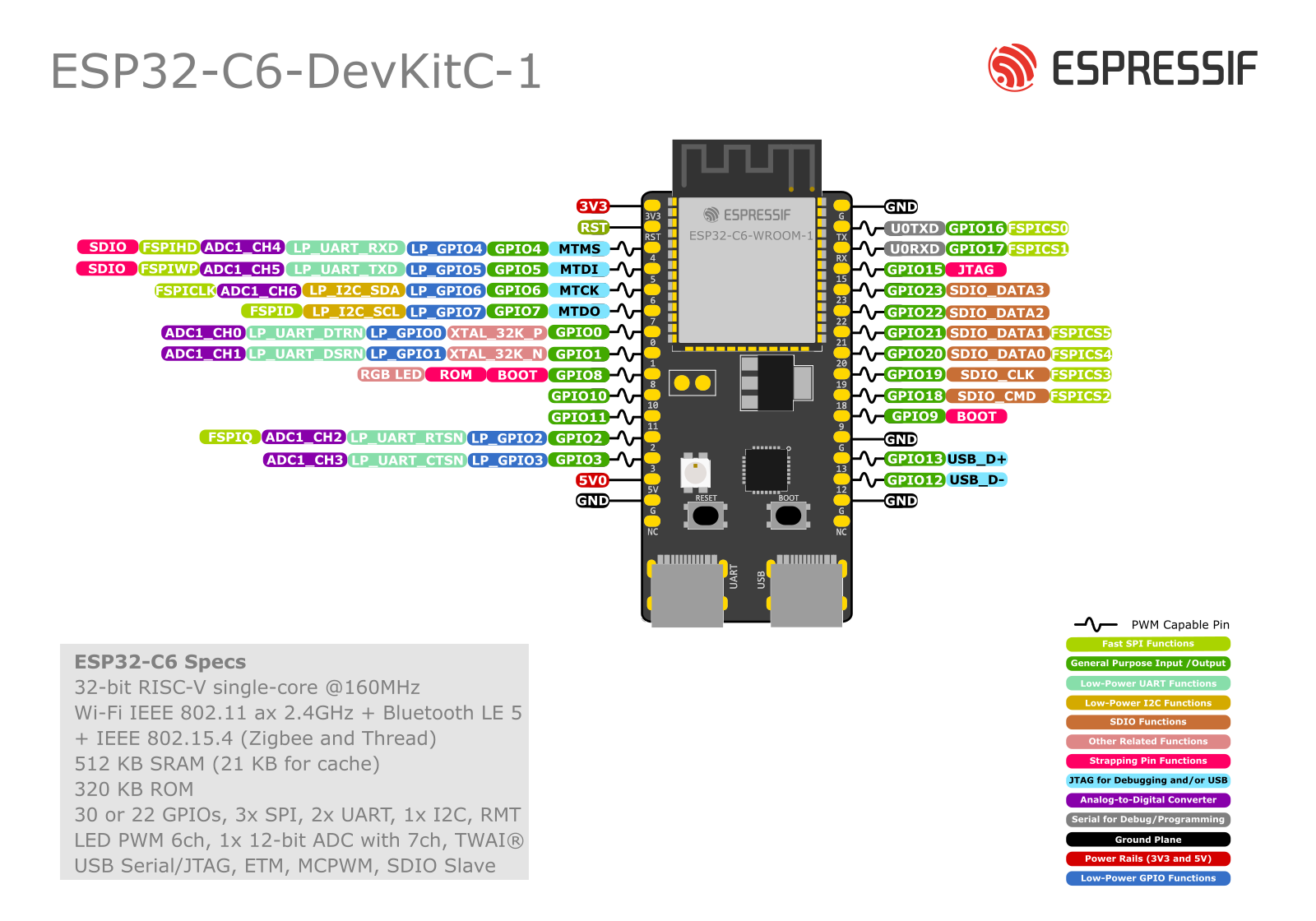
The pinouts won't help. UART is connected to
UART-USBbridge (a small IC near the USB ports). So when passing thewith_rxandwith_txto the driver, we must choose the GPIOs hardwired to the UART-USB bridge. These are GPIO16, GPIO17. For sending to GPIO-header-pins (those on the sidelines) we could pass any GPIO (but not when using the bridge.)
======!Spoiler Alert!====== (click for a solution)
There are many other details in the main.rs file, but the most critical is to make sense of this snippet:
let uart_config = uart::Config::default()
    .with_baudrate(115200)
    // ... other settings

let mut uart = Uart::new(peripherals.UART0, uart_config)
    //   driver^^^^^^^^^       periph^^^^^ config^^^^^^
    .expect("Should set up the driver.")
    // Route through the UART-USB bridge
    .with_tx(peripherals.GPIO16)
    .with_rx(peripherals.GPIO17);
That is another boilerplate we can think of: init device, grab peripheral, pass it to a driver along with its config.
A list of some of the peripherals is:
# (Most of these are unstable)
GPIO0-23, GPIO27 peripheral singleton
I2C0 peripheral singleton
I2S0 peripheral singleton
LEDC peripheral singleton
RNG peripheral singleton
SPI0-2 peripheral singleton
TIMG0-1 peripheral singleton
UART0-1 peripheral singleton
USB_DEVICE peripheral singleton
WIFI peripheral singleton
Exercise
- Access
exercises/uart/src/main.rs. The comments within will guide you through. - If not installed install
screen(for examplesudo apt install screen). - Before running it, note that we exit
screenwithCtrl+a+k(then pressingywhen prompted for it). - After flashing the board (any USB port) connect it through ch343 (or UART) tagged port.
- Run
screen <device_path> <baud_rate>.<device_path>is probably/dev/ttyACM0on Linux and/dev/tty.usbmodem0MacOS.- To be sure, list them with
ls /dev/tty*and try to figure out which one is the board. <baud_rate>must match the rate in the code. For example115200.
- Remember to press the RESET board button once.
- Try the echo server by typing in the keyboard, and send with Enter key.
Note
A solution is provided in
examples/uart.rs.
Imagining a projects
The esp32-c6 board has 2 UARTs: UART0 and UART1.
Technically, we could use UART0 just as we did, and UART1 could other GPIOs connected to GPIO-header-pins. By linking this to USB-UART converter and this in turn to a laptop, we could chat.
Two laptops could chat via the board.
Suggested Reading
- This is a good time to check
esp_hal, especially their peripherals section, and anything you find interesting.