I2C
I2C (inter-integrated communication) is a protocol and also a peripheral. We are concerned with the protocol.
"inter" in the name refers to within the board, "integrated" refers to integrated-circuits. In other words: communication between multiple integrated circuits within a board (or short distances).
Yet, devices supporting I2C need hardware that understands the protocol rules. Here, we will focus on its usage and most relevant concepts.
Note
An integrated circuit (IC) is an extremely packed, microscale version of a circuit. We could build one with wires, resistors and other components (and tons of effort).
ICs are the "black squares" in the PCB, but are not always visible, for example those within the MCU, or inside a sensor.
I2C is within the Synchronous Serial Communication umbrella:
- It is Serial because it transmits one bit at a time.
- It uses two lines: a serial clock-line (SCL) and a serial data-line (SDA).
- The SCL makes it a synchronous protocol.
The complete diagram is in this document (section 2.1), but a similar one from Wikipedia is shown below:
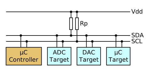
By Tim Mathias - Own work, CC BY-SA 4.0, Link
-
SDA is the Serial Data line, the road data travels on (in any direction). SCL is the Serial Clock line, which times when to read-from or write-to SDA.
-
The Vdd line pulls up the voltage in the SDA and SCL lines. There is a GND line as well, omitted here.
-
All the coloured blocks are devices, 3 can be targets only, one can be controller only.
µCmeans microcontroller, and Rp are resistors.
The last bit of terminology are the roles:
- Controller (formerly master): initiates communication. Microcontrollers are always in the controller role.
- Target (formerly slave): the target of the controller. Most devices –except MCUs– are targets.
And the modes: whichever the role is, a device can either be the receiver or the transmitter of data.
Communication
The high level view of the protocol is:
- A controller broadcasts START bit.
- It then broadcasts a target device address (usually 7 bits).
- Then sends a single bit where 0 receiver, 1 means transmitter.
- If the broadcasted address matches the ID of a target, the target replies with an acknowledgement and the communication starts.
- Now 8 bits of data are sent (either direction). The receiver always sends an acknowledgment bit.
- This step can repeat many times.
- No other device will transmit data during this time. It's "locked".
- Finally the controller broadcasts a STOP bit, and the bus is unlocked.
Here, most bits are sent through SDA, but the SCL also helps define when communication starts and ends, and times when to read from SDA.
The speed of the communication is a bit faster than UART's deppending on the mode, in the order of 10 KBps to 100 KBps.
For curiosity
- Search for "OLED I2C", or just any sensors. Many will support this or some of the already-learnt protocols. For I2C there will be a Vdd, GND, SDA, SCL lines, as expected.
- Don't buy more stuff! It's just to learn. You may even have some sensor supporting I2C already.
Suggested Reading
- I2C Protocol: explaions the protocol in a bit more detail than done here.
- Texas Instruments I2C subsection 2.1 (specially the schematic they have is quite good).