Blinky
We will now create the iconic blinky.
Let's access the project with cd exercises/blinky.
On esp32-c6 board there is no regular LED connected, instead there is an addressable LED which works differently and is beyond the scope of this book.
Instead, we will use a regular LED and a resistor, and build a circuit controlled with the GPIO pin headers.
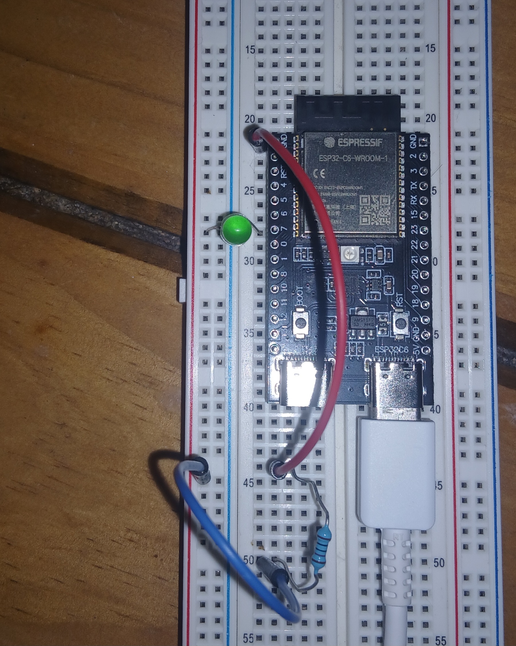
esp32-c6, wiring the LED
Wire up the board as shown on the previous image:
- Start wiring from
GNDpin header (red wire). - From there to the resistor (220mΩ or larger, without it the LED blows up).
- From the other leg of the resistor to the LED (blue wire).
- Finally, the LED connects to pin-header 7 (the long LED-leg is on 7).
Let's reconsider our boilerplate:
#![no_std]
#![no_main]

use esp_backtrace as _;
use esp_println::println;
use esp_hal::{main, Config};

esp_bootloader_esp_idf::esp_app_desc!();

fn main() -> ! {
    let peripherals = esp_hal::init(Config::default());
}
And now we ask ourselves:
- Which peripheral can we use to control pin-headers' electric state?
- We can use the
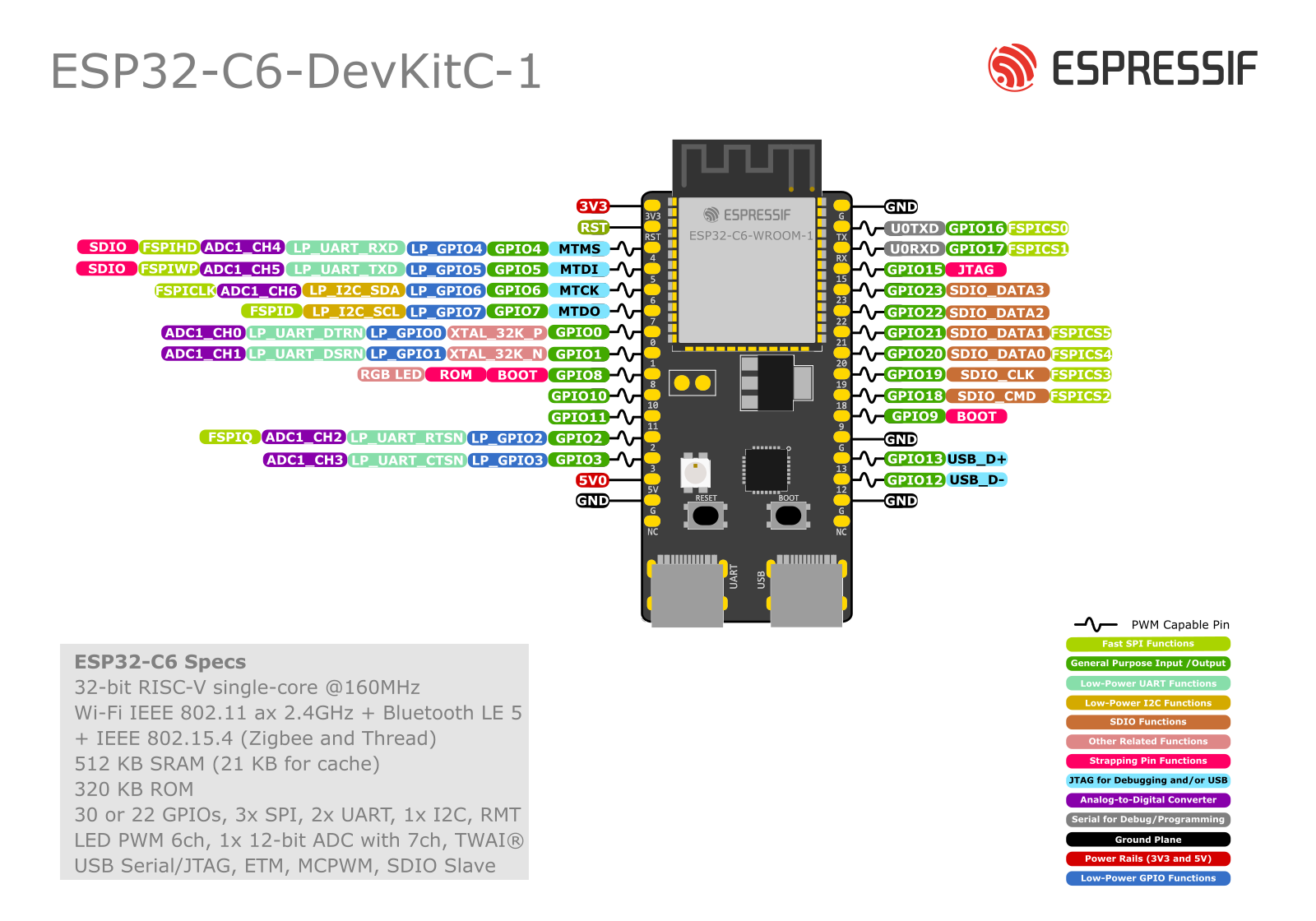
peripherals.GPIOXwhereXis the same number than the pin-header we need. - In this case, it's GPIO7, labelled 7. Always check the pinouts.
Warning
The PCB labels are written below the headers! So GPIO7 is not mapped onto header 6 (as a quick look might suggest), but on header 7.
- We can use the
- Which driver can we use to communicate with it?
- We can use the
Inputand / orOutputdrivers.
- We can use the
Exercise
- Open the file
src/main.rs, take some time to read the code. - Create
OutputConfigwith default configuration.- Hint: it implements
Default.
- Hint: it implements
- Toggle the
ledwith 3500ms delay.
The exercises/blinky/examples/blinky.rs contains a solution.
You can run it with the following command cargo run --example blinky --release.